
The VIN pin can be used to directly power the ESP32 and its peripherals, if you have a regulated 5V power supply. There are two power pins: the VIN pin and the 3V3 pin. The strapping pins function normally after reset release, but they should still be used with caution.
Esp8266 spi arduino code#
However, if peripherals are connected to these pins, you may encounter issues when attempting to upload new code or flash the ESP32 with new firmware, as these peripherals prevent the ESP32 from entering the correct mode. On most development boards with built-in USB/Serial, you don’t need to worry about the state of these pins, as the board puts them in the correct state for flashing or boot mode.

I use this Arduino Mega Board with build in ESP8266: After flashing the. Depending on the state of these pins, the ESP32 will enter BOOT mode or FLASH mode at power on. The MCP23S17 uses SPI while the MCP23017 uses I2C to communicate with the. The OLED display stops working.These pins are used to put the ESP32 into BOOT mode (to run the program stored in the flash memory) or FLASH mode (to upload the program to the flash memory). !! - Problem -: when ever I try to set input or output for LED or pushbutton, LoRa Based Low Power GPS Tracker with Arduino & ESP8266. But basically all of them has same pinout as LoRa SX1278 is an SPI module. Sending Sensor Data Wirelessly with LoRa SX1278 & Arduino: Check Here.

color sensor Setting frequency-scaling to 20% Interfacing SX1278 (Ra-02) LORA Module with Arduino: Check Here 2. So today, we are going to see the SPI Flash memory (NOR. Thus using the Arduino SPI API, it should work, like all other devices (the ESP32 Arduino Core implementation conforms to the API defined by Arduino, of course I would check if your board's pinout corresponds to the Espressif defined ESP32 pinout).
Esp8266 spi arduino serial#
The ESP8266 is perhaps the most versatile serial module to connect 'things' at the Internet, that why it is so popular in the world of IoT.
Esp8266 spi arduino how to#
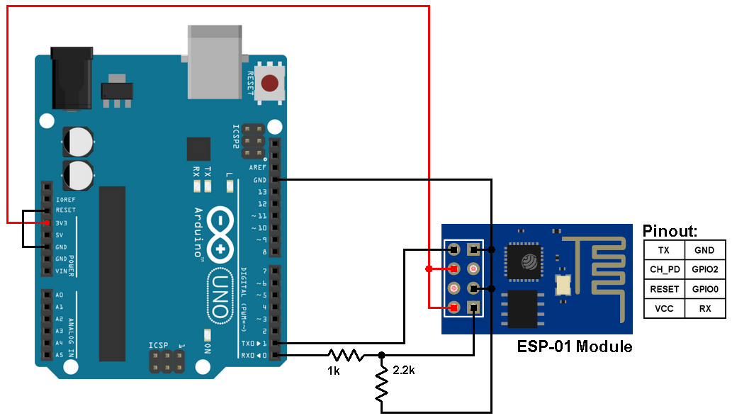
In this This first tutorial you will learn how to set-up and test the module connected to an Arduino. Pero lo que está ocurriendo con el ESP8266, puede reventar las nuevas tendencias de muchos sectores. This is the part 1 of 3 instructables to help you to use the ESP8266 with Arduino. Acercaba de una manera sencilla el IoT a la población civil. Serial.begin(115200) //I'm not using uart, using these pins for push button and LED instead The answer is pretty simple: internal flash has a short life for the write cycle, but flash memories like Winbond (or other) exist that, instead of having one hundred thousand cycles, have millions of write cycles and can be used like data logging. If you worked with OLED Displays (either I C or SPI type) before, then you probably would have downloaded the necessary libraries for Arduino IDE. Assuming that you use the ESP32 Arduino Core, under the docs it is written that SPI is has a suppported Arduino API implementation. Cuando salió el Arduino MKR1000, afirmé que revolucionaría el mundo de los objetos conectados, sobre todo por la facilidad de uso que caracteriza a estas placas. Using uart rx and tx pins for push button and LED instead of serial debug #define _CS 4 //GPIO4 (D2) cable select (SS) The OLED library I'm using for some reason makes me use GPIO4 and GPIO5 for the MISO and SS, instead of the regular HSCLK(GPIO14) and HMISO(GPIO12). Same effect, and I'm sure GPIO15 effects SPI. one is used for the external flash memory, second is on pins labeled D5, D6, D7 on NodeMcu. Some things I've tried: moving the LED and push button to GPIO0 and GPIO15.

I've run into these types of issues before probably because the ESP8266 is multiplexing some pins, but I didn't think RX and TX (GPIO3 & GPIO1) serial pins would be effected by SPI, since I'm pretty sure I've used SPI devices and enable serial uart for debug before. 1) First, make sure you include the SPI library in your code. Briefly, to use HSPI and VSPI simultaneously, you just need to. You can use the default HSPI and VSPI pins or use custom pins. As soon as I try to declare another pin as INPUT or OUTPUT for use as push button or LED, the SPI seems to stop working (the OLED display becomes blank after download). To communicate with multiple SPI peripherals simultaneously, you can use the ESP32 two SPI buses (HSPI and VSPI). The microSD card communicates with the ESP32 via SPI communication protocol. The program works fine when I only have the OLED display and the color sensor going. analogRead in time HTTP server library for ESP8266/ESP32 Arduino cores. This diagram below lays out my pin mapping. On an ESP8266 (nodeMCU), I have the following: I'm having trouble using GPIO3 and GPIO1 (uart tx and rx pins) on an ESP8266 for basic discrete input & output when I'm already using other pins for SPI.


 0 kommentar(er)
